Beam and bolting construction system and method
Patent No.: US11203865B2, US20210062504A1, US11603658B2
Abstract
Beam segments made of a somewhat compressible material may be arranged with the top surface of each beam segment substantially in contact with the bottom surface of a next beam segment between a first beam segment and a last beam segment. A plurality of bolt bores extends between the top and bottom surfaces of each of the beam segments in substantial alignment through each of the beam segments. The bolt bores are spaced apart to receive corresponding bolt segments and tightening fasteners compressed between the first beam segment and the last beam segment. The beam segments may be compressed to form a combined beam structure that forms a building structure unit. The combined beam structure may be joined with other combined beam structures to form walls and floors for a building structure.


Description
This non-provisional application claims priority as a continuation-in-part of U.S. patent application Ser. No. 17/095,181, filed on Nov. 11, 2020, the contents of which are incorporated herein by reference. This non-provisional also claims priority of U.S. patent application Ser. No. 15/986,605, filed on May 22, 2018, the contents of which are incorporated herein by reference. This non-provisional application claims priority of Ser. No. 65/539,556, by the same inventor, filed Aug. 1, 2017, the contents of which are incorporated herein by reference.
Background
Like nearly all other areas of knowledge and commerce, the field of dwelling construction is subject to continual improvements in techniques, use of materials, and related structural designs. This is certainly the case in the construction of dwellings such as cabins and small houses.
Although the concept of wooden dwellings goes back into prehistory, these have always been subject to problems, both in the construction methods and in the resulting products. For example, there are problems with traditional “log cabins” with respect to finding sufficiently uniform logs and requiring caulking materials (often requiring frequent renewal) to protect the inhabitants from the elements.
Wood constructions have many advantages, particularly since natural woods, with the exceptions of some hardwoods, have at least some degree of flexibility and compressibility. This allows for better weather sealing, and for better resistance to earthquake and wind damage. Better methods of improving these aspects are highly desirable.
Accordingly, there is significant room for improvement and a need for stronger and more easily constructed walls and frames for buildings.
Summary
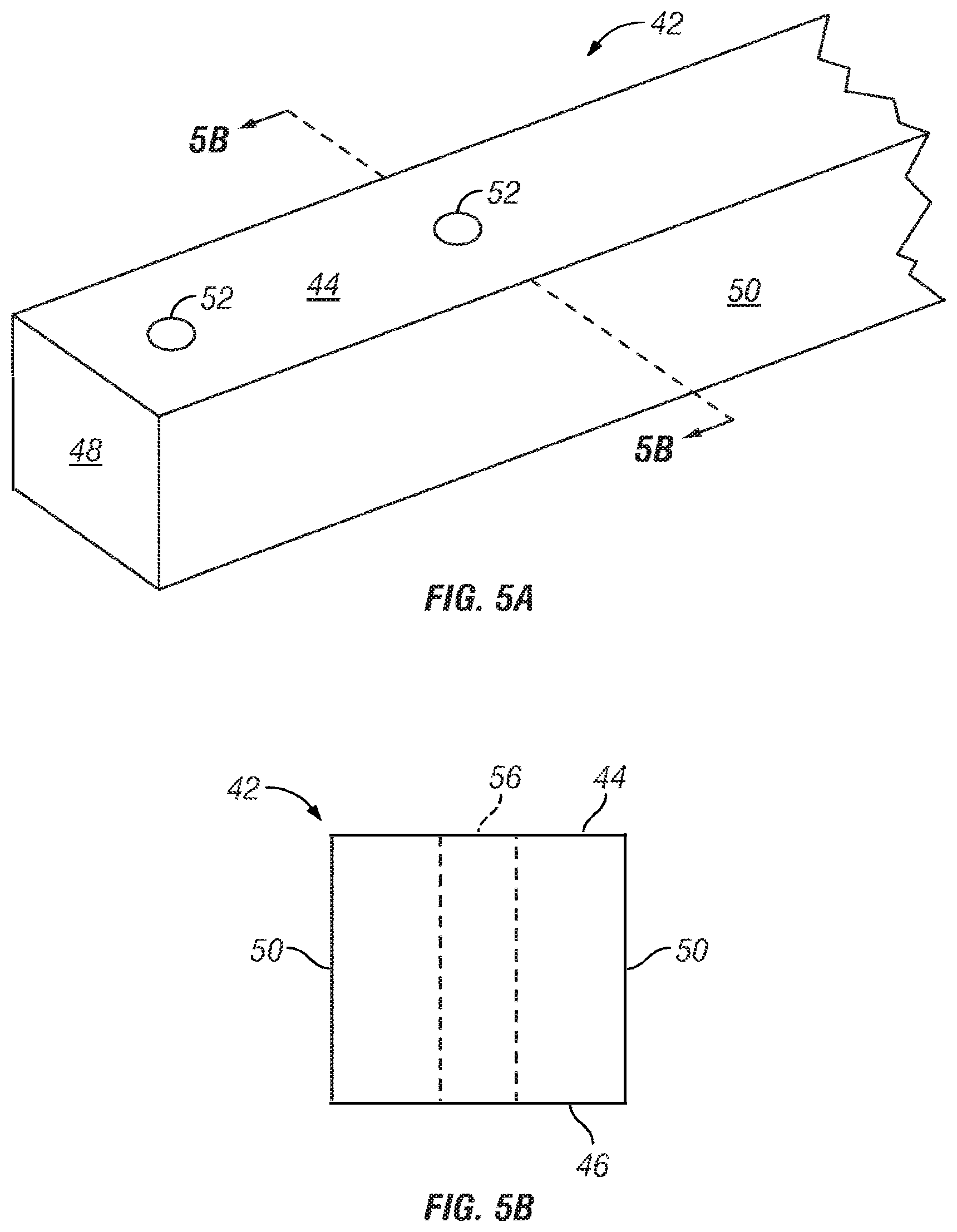
In view of the above, a combined beam structure includes a plurality of beam segments, each beam segment having a top surface and a bottom surface and made of a material that is at least slightly compressible. The plurality of beam segments is arranged with the top surface of each beam segment substantially in contact with the bottom surface of a next beam segment between a first beam segment and a last beam segment. A plurality of bolt bores extends between the top and bottom surfaces of each of the plurality of beam segments in substantial alignment through each of the plurality of beam segments. A plurality of bolt segments extends through corresponding bolt bores, and a plurality of tightening fasteners fasten to the bolt segments to apply compression between the first beam segment and the last beam segment.
In one aspect, the combined beam structure includes a joint side corresponding with a joint end portion of each of the plurality of beam segments. The joint end portion of each beam segment in a first subset of beam segments extend a distance from the joint end portion of each beam segment in a second subset of beam segments. The beam segments in the first subset of beam segments are arranged as alternating layers with the second subset of beam segments forming a staggered pattern of joint end portions at the joint side of the combined beam structure.
In another aspect, the combined beam structure is a first combined beam structure configured to couple with a second combined beam structure. The joint side is a first joint side of the first combined beam structure. The second combined beam structure is formed of another plurality of beam segments having a second joint side corresponding with joint end portions of the other plurality of beam segments arranged to form a staggered pattern on the second joint side of the second combined beam structure. The staggered pattern of the first joint side of the first combined beam structure interlocks with the staggered pattern of the second joint side of the second combined beam structure to form a wall structure junction between the first combined beam structure and the second combined beam structure.
In one example, the wall structure junction forms a wall corner between the first combined beam structure and the second combined beam structure extending at an angle with the first combined beam structure.
In an example wall corner, the first combined beam structure and the second combined beam structure form a substantially 90-degree angle.
In another example, the wall corner is formed with the joint end portions of the first combined beam structure extending to interlock with the joint end portions of the second combined beam such that the joint end portions of the first combined beam structure are flush with a planar surface of a wall structure formed by the second combined beam structure.
In another example, the wall corner is formed with the joint end portions of the second combined beam structure extending to interlock with the joint end portions of the first combined beam such that the joint end portions of the second combined beam structure are flush with a planar surface of a wall structure formed by the first combined beam structure.
In another example, the wall corner is formed with the joint end portions of the first combined beam structure extending to interlock with the joint end portions of the second combined beam such that the joint end portions of the first combined beam structure extend beyond a planar surface of a wall structure formed by the second combined beam structure.
In another example, the wall corner is formed with the joint end portions of the second combined beam structure extend to interlock with the joint end portions of the first combined beam such that the joint end portions of the second combined beam structure extend beyond a planar surface of a wall structure formed by the second combined beam structure.
In another aspect, the plurality of bolt bores in each of the plurality of beam segments includes a junction bolt bore in the joint end portion of each of the plurality of beam segments where the junction bolt bore aligns with a junction bolt bore at a joint end portion of the second combined beam structure at the wall structure junction.
In another aspect, the plurality of bolt bores in each of the plurality of beam segments includes an inner junction bolt bore disposed an inner junction distance from the junction bolt bore. The inner junction bolt bores of beam segments that extend to form the staggered pattern align with the junction bolt bores of non-extending beam segments.
BRIEF DESCRIPTION OF THE DRAWINGS
The purposes and advantages of example implementations will be apparent from the following detailed description in conjunction with the appended drawings in which:
FIG. 1 is a front plan view of an example dwelling constructed using examples of combined beam structures.
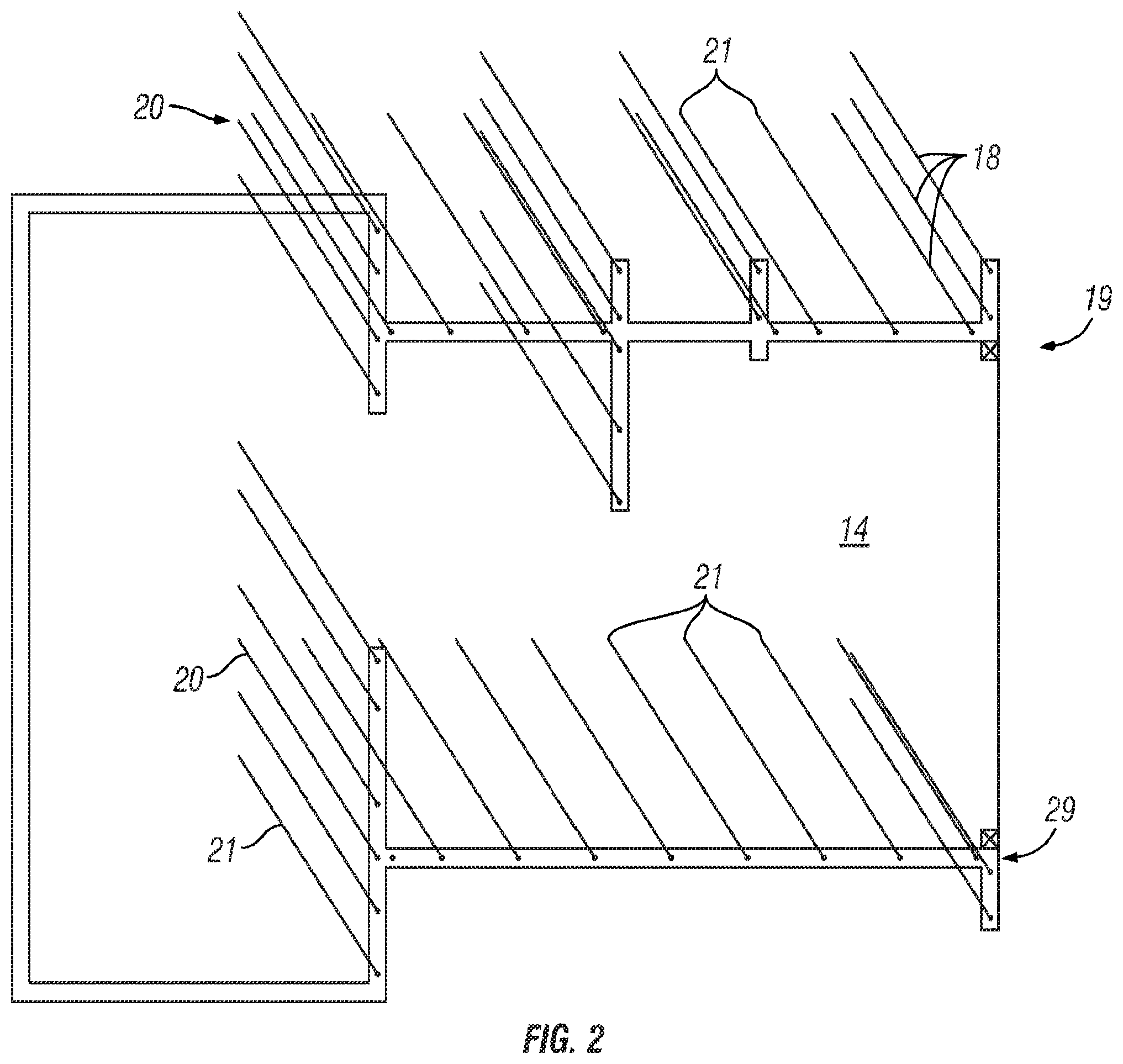
FIG. 2 is a perspective view of a construction site at an early stage, prior to installation of any beams, showing a typical bolting array.
FIG. 3 is a plan view of the left side/end of the example dwelling.
FIG. 4 is a rear plan view of the example dwelling.
FIG. 5A is a truncated perspective view of an example beam for use in an example of a combined beam structure.
FIG. 5B is a cross sectional view of the beam of FIG. 5A, taken along line B-B.
FIG. 6 is a plan view of the right side of the example dwelling, showing a roof mounting approach.
FIG. 7 is cutaway side view of an alternate dwelling, showing another roof mounting approach.
FIG. 8 is a fanciful cross-sectional illustration of a segment of a wall showing an interstitial bolt anchored in the foundation slab and extending upward to pass through the bolt holes in the beams.
FIG. 9 is a fanciful cross-sectional view of a section of the foundation slab, an elongated bolt anchored in the slab and extending through bolt holes, and an alternate washer plate providing an external spacing and securing bracket.
FIG. 10 is a side view of a prototype partial corner section of two very short exterior walls, showing the layering and bolting techniques.
FIG. 11A shows a system for precise anchoring of an elongated threaded bolt in the foundation slab.
FIG. 11B is a top plan view of a top (or bottom) mounting bracket for the system of FIG. 11A; and
FIG. 12 shows in examples A, B, C, and D, four envisioned corner bracing configurations.
FIG. 13A is a front plan view and a side section view of an example implementation of a combined beam structure.
FIG. 13B is a front plan view and a side section view of another example implementation of a combined beam structure.
FIG. 14 is an isometric view of an example of a wall junction structure formed as a wall corner.
FIG. 15 illustrates an example of a bolt segment.
FIG. 16 is an isometric view of an example building structure.
FIG. 17 illustrates another example building structure and a top view of an example combined beam structure used as a floor.
FIG. 17A is a top cross-sectional view of the building structure in FIG. 17 at cross-section 17A.
FIG. 18 illustrates example mechanisms for attaching a bolt segment to a combined beam structure configured to function as a floor.
FIG. 19 illustrates another example implementation of a combined beam structure and an alternative mechanism for providing a foundation for the combined beam structure in a building structure.
FIGS. 19A and 19B are cross-sectional views of portions of the alternative mechanism for providing a foundation shown in FIG. 19 at cross-sections 19A and 19B, respectively.
Full Patent can be viewed via Google Patent Search to learn more.
Registered Trademarks:
Word Mark: BOLTLAMA
Goods and Services: IC 019. US 001 012 033 050. G & S: Non-metal building materials, namely, bolted wood beams; Non-metal building materials, namely, rough and dressed lumber; Non-metal shelter structures; Structural timber
Standard Characters Claimed:
Mark Drawing Code: (4) STANDARD CHARACTER MARK
Serial Number: 90522977
Filing Date: February 10, 2021
Current Basis: 1B
Original Filing Basis: 1B
Published for Opposition: October 12, 2021
Owner: (APPLICANT) RedRider, LLC LIMITED LIABILITY COMPANY CALIFORNIA
Attorney of Record: Michael K Bosworth
Type of Mark: TRADEMARK
Register: PRINCIPAL
Live/Dead Indicator: LIVE
Word Mark: REDRIDER
Goods and Services: IC 019. US 001 012 033 050. G & S: Log homes sold in kit form; Non-metal building materials, namely, bolted wooden beams; Non-metal shelter structures
Standard Characters Claimed:
Mark Drawing Code: (4) STANDARD CHARACTER MARK
Serial Number: 90522986
Filing Date: February 10, 2021
Current Basis: 1B
Original Filing Basis: 1B
Published for Opposition: October 12, 2021
Owner: (APPLICANT) RedRider, LLC LIMITED LIABILITY COMPANY CALIFORNIA 4250 Verdigris Circle San Jose CALIFORNIA 95134
Attorney of Record: Michael K. Bosworth
Type of Mark: TRADEMARK
Register: PRINCIPAL
Live/Dead Indicator: LIVE
PCT Approval